NASA Jet Propulsion Laboratory
Power Distribution Systems and Optimal Control
I had an 8 month long internship at the NASA Jet Propulsion Laboratory robotics division working with the Steep Terrain Mobility team. There, I took ownership of the electrical system for an in-development rover and researched gait transition algorithms.
Gait Transition Algorithms
The Steep Terrian Mobility Team was interested in a multi-modal robot concept which had multiple modes of locomotion. Said robots can be seen below.
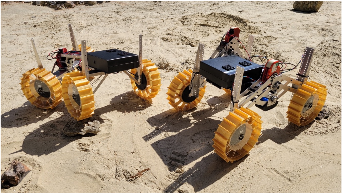
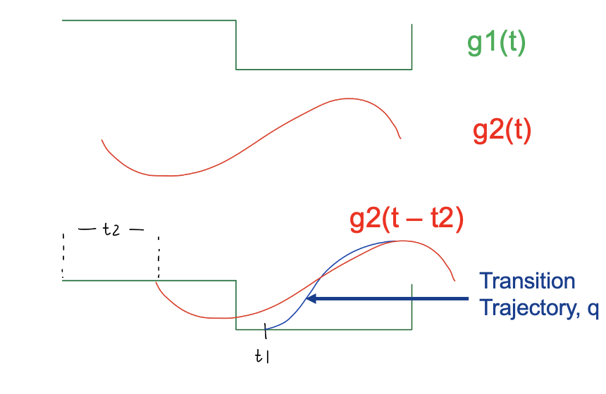
I thought that the transitions between these locomotion modes would be of interest so I began a side-project looking into them. I landed on a couple trajectory optimization methods which I compared with experiments. The full results can be seen in Trajectory Optimization Methods for Energy Efficient Gait Transitions on Multi-Modal Robots. The idea was to mantain joint and workspace continuity + minimize energy consumption during gait transitions.

Power Distribution Boards
I was also in charge of creating the electrical system for the new rover. I used my prior experience with PCBs to create Power Distribution Boards. One was responsible for taking in battery voltage and distributing it to motors and step-down converters. For safety, it included overcurrent protection and power monitoring. The second board was full of step-down converters for the different voltages needed by the robot’s components. It also included overcurrent protection and power monitoring. After designing the boards, I assembled and tested them.
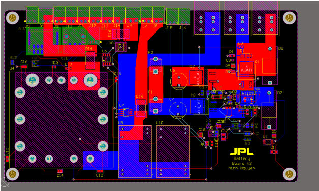
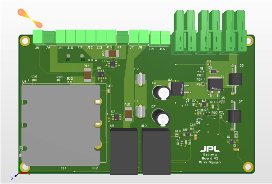
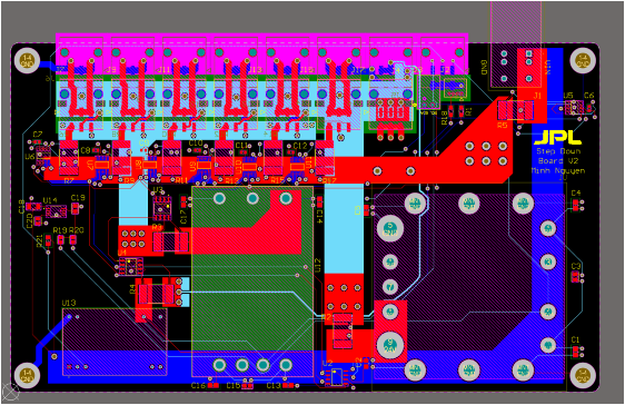
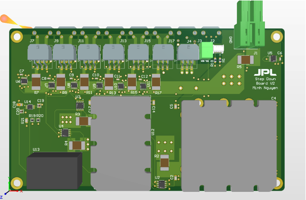
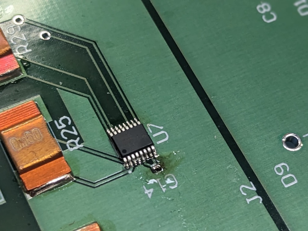
I had a lot of fun with these boards and actually hand-soldered my smallest component yet (with a lot of trouble)! An 0102 capacitor which is below the IC in the bottom picture.
